7 Best Solutions to Common Problems in Steel Structures

Time:2026-10-18 Author:Madeline
0%

Steel structures are strong, efficient, and adaptable, but they are not maintenance-free. Engineers and contractors still face corrosion, buckling, fatigue, weak connections, fire exposure, and erection errors. These problems often begin with small details, such as trapped water inside an unsealed joint or a bolt installed without proper tightening.

So, what are common problems in steel structures? The answer depends on design quality, material selection, fabrication accuracy, site conditions, and inspection discipline. A roof beam may appear sound while hidden corrosion reduces its thickness. A column may carry its design load but fail through unexpected buckling. These risks require practical judgment, not only calculations.

W. F. Baker, a respected structural engineer, has said, “The structure is the architecture.” His observation reminds us that structural performance depends on how every component works together. A connection is not merely a drawing detail. It transfers forces through plates, bolts, welds, and supporting members.

This guide, “7 Best Solutions to Common Problems in Steel Structures,” examines reliable ways to prevent and correct these failures. It considers protective coatings, drainage, connection detailing, fire protection, quality control, and regular inspections. Each solution reflects established engineering practice and real construction experience.

No checklist is perfect. Site conditions change. Human mistakes happen. That is why competent engineers must verify assumptions, document inspections, and question unusual movement, cracking, vibration, or rust stains. Small warning signs deserve attention. Sometimes, the overlooked detail controls the entire structure’s safety.
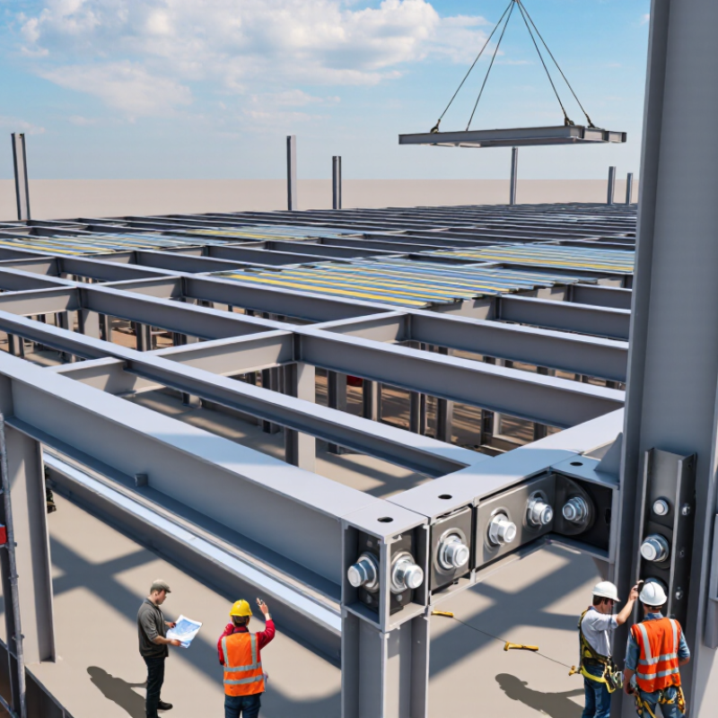
7 Best Solutions to Common Problems in Steel Structures

Controlling Corrosion Through Protective Steel Treatments

Corrosion is one of the most persistent problems in steel structures. Moisture, salt, pollutants, and trapped dirt can attack exposed steel quickly. Protective treatment begins with a clean, dry, and properly prepared surface. Oil, mill scale, rust, and loose paint must be removed before coating. Abrasive blasting is effective, but power-tool cleaning may suit smaller repairs.

A zinc-rich primer can provide sacrificial protection when steel becomes slightly exposed. Epoxy coatings create a strong barrier against water and chemicals. A durable topcoat helps resist sunlight, temperature changes, and abrasion. Coating edges, welds, bolts, and drainage points require extra attention. These areas often fail before broad, flat surfaces. Inspectors should record surface conditions, humidity, steel temperature, and dry-film thickness during application. Small records prevent large disputes later.

No coating plan is perfect. A missed weld can become a hidden corrosion site. Poor drainage can defeat an expensive treatment. Regular inspections should check blistering, cracking, rust staining, and damaged edges. Repairs must remove corrosion before adding new coating layers. Protective systems also need compatible materials and correct curing time. Rushing the work is tempting, especially during short maintenance shutdowns. It often creates a weaker result. In cold or damp weather, coating performance may change, so site judgment remains essential.

7 Best Solutions to Common Problems in Steel Structures: Controlling Corrosion Through Protective Steel Treatments

Atmospheric corrosivity increases the risk of section loss, premature maintenance, and structural damage. The chart shows the upper first-year thickness-loss boundary for carbon steel in each ISO 9223 corrosivity category.

Protective approach: Select a suitable protective coating system, hot-dip galvanizing, weathering steel, cathodic protection, corrosion inhibitors, drainage-focused detailing, and scheduled inspection and maintenance. Values are classification boundaries from ISO 9223:2012 and are not guaranteed service-life predictions.

Preventing Buckling with Proper Design and Structural Bracing

7 Best Solutions to Common Problems in Steel Structures

Preventing Buckling with Proper Design and Structural Bracing

Buckling often begins quietly. A slender column may appear straight, yet small imperfections can rapidly reduce its load capacity. Proper design starts with effective length, slenderness ratio, and realistic restraint conditions. The European standard EN 1993-1-1, Table 6.2, uses imperfection factors ranging from 0.13 to 0.76 for different buckling curves. These values reflect how section shape, fabrication quality, and residual stress influence stability.

Bracing must create a dependable load path. Diagonal members, floor diaphragms, and rigid connections should transfer lateral forces without unexpected flexibility. The AISC 360-22 specification applies a 0.90 resistance factor for compression members under LRFD design. Engineers should still check second-order effects, including P-Δ behavior, especially in tall frames. A brace that looks strong may fail through connection slip or weak anchorage.

Site experience reveals uncomfortable gaps between drawings and reality. Temporary bracing is often removed too early. Bolts may remain loose, and deck connections may not provide the assumed restraint. I have seen inspection teams trust analytical models more than actual site conditions. That habit needs correction. Independent checks, measured member alignment, and staged erection reviews can expose instability before loading begins. Conservative assumptions are useful, but they cannot replace careful observation.

Strengthening Weak Connections with Reliable Joint Details

Weak steel connections rarely fail because one bolt is obviously missing. More often, load paths become unclear at gusset plates, beam seats, splice plates, or welded end details. A connection may appear rigid while slip, prying, or local buckling develops behind the finish. In field inspections, dependable repairs begin with a measured survey, not a guessed detail. Check bolt diameter, hole size, edge distance, weld length, plate thickness, and visible distortion. Record cracks and corrosion with photographs and simple sketches. A small gap matters. Measure twice.

Reliable strengthening should improve the existing load path instead of adding steel randomly. Engineers may specify new bolts, thicker plates, stiffeners, cover plates, or supplemental welds after checking factored loads and connection stiffness. The detail must transfer tension, shear, and moment without creating another weak zone. Use qualified welding procedures, controlled bolt installation, and inspection records. Where access is limited, bolting may be more practical than field welding. Temporary shoring can protect workers and prevent movement during installation. Do not conceal a connection beneath fireproofing before inspection is complete.

Site conditions often challenge the drawing. Misaligned holes, trapped moisture, limited weld access, and old repairs can change the final detail. Drawings can mislead. Field reports often reveal that a neat calculation ignored practical fabrication limits. Allow realistic tolerances, drainage paths, and safe inspection access. Recheck the connection after loading, especially around new weld ends and bolt groups. Not every repair needs more steel; removing corrosion or correcting fit-up may restore the intended behavior. Independent review is valuable when the connection carries critical loads or has an uncertain history.

7 Best Solutions to Common Problems in Steel Structures - Strengthening Weak Connections with Reliable Joint Details
No. Common Problem Typical Symptoms Recommended Solution Reliable Joint Details Typical Materials and Parameters Key Verification Checks
1 Insufficient bolt capacity in a moment or shear connection
  • Slotted or elongated bolt holes
  • Slip under service loading
  • Local plate distortion around bolt holes
Increase the connection capacity with additional high-strength bolts and thicker connection plates.
  • Add bolts symmetrically about the load path.
  • Use suitable edge and end distances.
  • Install splice or cover plates on both sides where eccentricity is significant.
Structural bolts S275/S355 plates
  • Common bolt diameters: M16–M24
  • Use preloaded bolts where slip resistance is required.
  • Design hole clearances and spacing to the governing steel design standard.
Check bolt shear, tension, bearing, block tearing, net-section rupture, plate bending, and slip resistance where applicable.
2 Weak or undersized end plates in beam-to-column joints
  • Excessive end-plate bending
  • Permanent rotation after loading
  • Visible prying action near bolt rows
Replace or supplement the end plate with a thicker, stiffened plate designed for the required moment and shear.
  • Extend the plate to provide adequate bolt-row lever arms.
  • Add triangular continuity stiffeners where flange forces enter the column.
  • Detail welds for force transfer rather than nominal attachment only.
End plate Continuity stiffener
  • Typical plate thickness range: 12–25 mm, subject to calculation.
  • Use continuous welds where force flow requires full development.
  • Maintain access for bolt tightening and inspection.
Verify component stiffness, bolt-row tension, prying forces, column flange bending, panel-zone resistance, weld strength, and joint rotation capacity.
3 Column panel-zone yielding or excessive deformation
  • Diagonal yielding in the column web
  • Large beam-to-column joint rotations
  • Distortion visible between column flanges
Strengthen the panel zone with doubler plates or increase the effective web resistance with properly welded reinforcement.
  • Fit doubler plates tightly between column flanges.
  • Use full-length welds sized for the transferred shear.
  • Provide continuity plates when beam flange forces require direct support.
Doubler plate Continuity plate
  • Plate thickness is commonly selected to supplement the existing web.
  • Use compatible steel grades and qualified welding procedures.
  • Stagger weld terminations where fatigue-sensitive details are present.
Check panel-zone shear, column web local yielding, column flange bending, weld transfer, stability, and compatibility of deformation.
4 Weld cracking, poor fusion, or inadequate weld size
  • Surface cracks or undercutting
  • Incomplete fusion indications
  • Crack growth near weld ends or abrupt transitions
Remove defective weld metal, repair the joint using a qualified welding procedure, and improve the connection geometry where stress concentrations exist.
  • Use smooth weld transitions and avoid abrupt weld terminations.
  • Provide weld access holes where required for complete joint penetration.
  • Sequence welding to limit distortion and residual stress.
Repair weld NDT inspection
  • Use qualified procedures and appropriately classified consumables.
  • Typical inspection methods include visual testing, magnetic-particle testing, ultrasonic testing, or radiographic testing.
  • Preheat and interpass temperatures depend on steel grade and thickness.
Verify weld throat, effective length, base-metal strength, fatigue category, weld quality, distortion, and nondestructive examination results.
5 Local web crippling or flange yielding at concentrated reactions
  • Web buckling beneath a support or point load
  • Flange indentation
  • Crushing near bearing plates or brackets
Distribute the concentrated force with bearing stiffeners, web doubler plates, or a larger load-transfer plate.
  • Place stiffeners directly in line with the reaction or applied force.
  • Extend stiffeners to the loaded flange where force transfer requires it.
  • Provide close-fitting contact and weld both sides when needed.
Bearing stiffener Web doubler
  • Use paired stiffeners for balanced load transfer.
  • Stiffener thickness and width depend on the reaction, web slenderness, and stability requirements.
  • Detail welds for compression, tension, and shear transfer.
Check web bearing, web crippling, local yielding, flange bending, stiffener buckling, weld resistance, and load dispersion into the member.
6 Connection slip, vibration, or fatigue-sensitive detailing
  • Movement under repeated service loads
  • Fretting marks around bolt holes
  • Cracks at weld toes, cope corners, or connection discontinuities
Use a slip-resistant joint where required and improve fatigue detailing by reducing stress concentrations and providing smoother force flow.
  • Use preloaded bolts with prepared faying surfaces for slip-critical applications.
  • Avoid sharp re-entrant corners and abrupt changes in stiffness.
  • Use generous cope radii and accessible weld profiles.
Preloaded bolts Fatigue detail
  • Faying-surface condition must match the assumed slip factor.
  • Use calibrated tightening methods and document installation.
  • Assess stress range and number of cycles for fatigue design.
Verify slip resistance, bolt pretension, surface condition, stress concentration, fatigue category, vibration response, and inspection requirements.
7 Corrosion-induced section loss at joints and base connections
  • Reduced plate or bolt-section thickness
  • Flaking steel and rust expansion
  • Water accumulation around crevices and base plates
Remove corrosion, restore lost section with engineered plates or weld repairs, and eliminate moisture traps through drainage and protective treatment.
  • Replace severely deteriorated bolts rather than relying on remaining section.
  • Use cover plates with sealed or continuously welded edges where appropriate.
  • Provide drainage paths and seal crevices that cannot be inspected.
Section restoration Protective coating
  • Measure remaining thickness with calibrated ultrasonic equipment.
  • Use compatible repair steel and qualified weld procedures.
  • Specify a coating system suitable for the exposure environment.
Check remaining net area, bolt capacity, plate buckling, weldability, load transfer during repair, coating condition, drainage, and future inspection access.

Improving Fire Resistance Through Thermal Protection Methods

Steel does not burn, but it can lose load-bearing strength quickly as temperatures climb. In a real fire, heat gathers around exposed flanges, joints, and connection plates. Thermal protection slows that rise and preserves valuable time for evacuation and firefighting. Reliable design begins with a tested fire-resistance assembly, not a coating selected from a sales sheet. Fire engineers review the required rating, section factor, ventilation, moisture, and maintenance access. Small details matter.

Common solutions include seven thermal defenses used alone or in combined assemblies.

Intumescent coatings swell into an insulating char when heated.

Spray-applied cementitious protection forms a thicker mineral shield around steel.

Board encasement creates a dry, replaceable barrier and clean finish.

Concrete encasement adds mass, but it increases weight and construction time.

Mineral wool systems reduce heat transfer around beams and columns.

Firestopping protects penetrations that could otherwise channel flames and hot gases.

Compartmentation limits fire spread and reduces the thermal demand on protected members.

No method is foolproof.

On site, surface preparation deserves as much attention as material selection. Oil, rust, dust, or trapped moisture can weaken adhesion and hide defects. Installers should measure dry-film thickness, record ambient conditions, and inspect difficult connection zones. Damaged areas need compatible repair, not a quick brush over the visible mark. Independent inspection and documented testing support compliance with the applicable building code. Still, specifications can miss reality. A crowded plant room, unexpected condensation, or later drilling may undermine a carefully designed system. That possibility deserves honest review during every inspection.

Reducing Fatigue Damage with Inspection and Load Management

7 Best Solutions to Common Problems in Steel Structures

Reducing Fatigue Damage with Inspection and Load Management

Fatigue cracks often begin near weld toes, bolt holes, and sharp geometry changes. Repeated traffic or machinery vibration slowly enlarges these small defects. During field reviews, engineers should inspect high-stress details closely, especially after unusual loading or visible deformation. Ultrasonic testing can reveal internal flaws that visual checks may miss. Inspection records should include photographs, crack dimensions, dates, and weather conditions.

Load management is equally important. Reduce unnecessary impact, vibration, and sudden load changes where practical. Operators can limit overloaded vehicles, uneven lifting, and repeated starts and stops. Structural engineers should compare real operating loads with the original design assumptions. Those assumptions may no longer match current use. A simple load log can expose patterns that drawings cannot show.

Tips: Mark crack locations on a sketch. Measure them consistently. Clean rusty surfaces before inspection. Never grind away evidence without engineering review. Schedule follow-up inspections based on crack growth risk, not convenience.

Inspection plans are not perfect. Fatigue damage may develop between scheduled visits, and access limitations can hide critical areas. That uncertainty deserves attention. A qualified engineer should evaluate findings, calculate remaining capacity, and set repair or monitoring intervals. Even a minor crack can become serious when heavy loads continue unchanged. Better decisions come from combining measured evidence, conservative judgment, and honest review of what the inspection could not confirm.

FAQS

What should be checked before strengthening a weak steel connection?

Measure bolt diameter, hole size, edge distance, weld length, and plate thickness.

Why can a connection look rigid but still be unsafe?

Slip, prying, or local buckling may develop behind finishes.

Which strengthening methods may improve an existing connection?

Engineers may specify new bolts, thicker plates, stiffeners, cover plates, or supplemental welds.

When is bolting more practical than field welding?

Bolting may suit areas with limited welding access or difficult site conditions.

What site conditions can change the repair detail?

Misaligned holes, trapped moisture, old repairs, and limited weld access can affect installation.

How can fatigue cracks be detected in steel structures?

Inspect weld toes, bolt holes, and sharp geometry changes near high-stress areas.

How can operators reduce fatigue damage?

Limit overloaded vehicles, uneven lifting, sudden starts, stops, and unnecessary vibration.

What should inspection records include?

Record crack locations, dimensions, photographs, inspection dates, and weather conditions.

How should follow-up inspections be planned?

Set inspection intervals according to crack growth risk, load severity, and access limitations.

Conclusion

Understanding what are common problems in steel structures is essential for maintaining safety, durability, and long-term performance. This article presents practical solutions for addressing major challenges, including corrosion, buckling, weak connections, fire exposure, and fatigue damage. Protective steel treatments, such as suitable coatings and regular maintenance, can help control corrosion and extend service life.

Proper structural design and bracing reduce the risk of buckling, while reliable joint details strengthen connections and improve overall stability. Thermal protection methods can enhance fire resistance by slowing the rise of steel temperatures during a fire. In addition, scheduled inspections, appropriate load management, and timely repairs help reduce fatigue damage caused by repeated stress. Together, these approaches provide a practical framework for improving the safety, reliability, and resilience of steel structures in demanding environments.

Madeline

Madeline

Madeline is a dedicated marketing professional with a wealth of expertise in our company's core offerings. With a keen understanding of the industry, she brings a unique perspective to her role, consistently delivering high-quality content that highlights the superior aspects of our products. As......