Designing a steel structure plant begins with more than choosing columns, rafters, and roof sheets. The process connects production needs, site conditions, structural performance, and long-term operating costs. A useful starting question is how to design a steel structure plant that supports today’s workflow without making future changes unnecessarily difficult.
Industry data shows why these choices matter. The World Steel Association’s sectoral steel-use data attributes about 52% of steel demand to buildings and infrastructure. Meanwhile, the 2024 Global Status Report for Buildings and Construction, published by the UN Environment Programme and Global Alliance for Buildings and Construction, estimates that buildings and construction account for 32% of global energy demand and 34% of energy-related carbon dioxide emissions. These figures are broad, not plant-specific. Still, they show why structural efficiency, material quantities, and the building envelope deserve early attention.
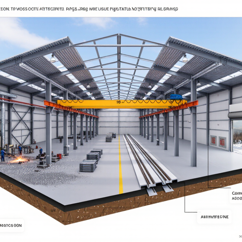
Real details shape the design. A 10-tonne overhead crane, a dusty fabrication bay, or a loading door exposed to winter winds can change framing, clearances, and ventilation requirements. Engineers typically assess these needs alongside soil information, local climate loads, fire protection, drainage, and applicable building codes. The exact priorities vary by site. That is easy to overlook.
A dependable design process brings owners, architects, and structural and services engineers together before drawings are fixed. It also records assumptions, such as future crane capacity and expansion space, so they can be reviewed rather than quietly treated as facts. No spreadsheet replaces a site walk. Nor should a preliminary layout be mistaken for a verified engineering design.
Set plant capacity from saleable output, not nameplate rate. For example, a 120,000-tonne annual target over 300 operating days requires about 400 tonnes daily. This is a planning example, not a universal benchmark. World Steel Association’s World Steel in Figures 2024 reports 1,892.5 million tonnes of crude steel production in 2023; that scale is context, not a plant-sizing rule. Translate your own output target into hourly flow, storage needs, and equipment downtime allowances.
Lay out the bay grid around the actual process route: furnace, finishing line, storage, and truck or rail access. A wide bay may ease handling but increase roof and crane-support demands. Set clear height from the largest lifted load, hook approach, crane headroom, and required maintenance access. Specify crane duty using expected load spectrum and operating cycles; ISO 4301-1 provides a classification framework. AISC Design Guide 7 also addresses industrial building planning and roof systems. Check crane reactions early with the structural engineer.
Tip: Sketch the heaviest load’s full travel path, including turns and parked equipment. Revisit assumptions after reviewing real shift data; estimates often miss maintenance stoppages. Allow for that uncertainty.
Design loads should reflect the plant’s actual use, not a generic warehouse template. Start with dead loads: steel framing, roof panels, insulation, fixed equipment, and permanently mounted services. Add live loads for storage, maintenance access, and occupied areas. Cranes and machinery need separate attention, including operating effects and support reactions.
Small details matter. A heavy process line can shift load into a few frames, while roof equipment may change local demands.
For wind, ASCE 7-22 provides criteria for selecting site-specific wind speeds and calculating pressure. Check risk category, terrain exposure, building enclosure, and internal pressure; large doors can make the last assumption especially important.
For seismic design, establish site class and mapped hazard parameters, then consider structural system, response factors, and effective seismic weight.
The NOAA National Centers for Environmental Information recorded 28 U.S. billion-dollar weather and climate disasters in 2023, with estimated losses of $92.9 billion. That report is not a design wind map, but it reinforces why local hazard assessment matters.
Even a tidy spreadsheet can hide a weak assumption. Recheck load paths, combinations, and uplift against the project’s geotechnical data and governing requirements.
ASTM A36 and A992 are both common choices for structural framing, but their strengths and typical uses differ. A36 has a specified minimum yield strength of 250 MPa (36 ksi). A992 provides 345 MPa (50 ksi) and is commonly specified for wide-flange shapes. Check the actual mill certificates and project specifications; grade alone does not describe every property that matters. A992’s controlled material requirements can support consistent design, while A36 remains useful for plates and other components.
Higher yield strength may allow smaller members, but it does not automatically make a plant lighter or cheaper. Column buckling, roof deflection, crane loads, connection design, and bracing can govern before steel strength does. Picture a long roof bay with heavy equipment: limiting movement may matter more than choosing the highest-strength grade. Weldability also depends on thickness, chemistry, and the approved welding procedure. I would not select by yield strength alone. That shortcut looks neat on paper, but it can miss fabrication and serviceability concerns. Have a qualified structural engineer compare member sizes, connections, availability, and total installed cost for the actual loads and layout.
| Design consideration | ASTM A36 | ASTM A992 | Implication for plant framing |
|---|---|---|---|
| Specified minimum yield strength, Fy | Typically 36 ksi (250 MPa) for shapes and plates up to 8 in. (203 mm) thick; requirements can vary with product and thickness. | 50 ksi (345 MPa) minimum; 65 ksi (450 MPa) maximum yield strength under the specification. | A992’s higher specified yield strength may reduce required member area where strength governs, subject to stability, serviceability, and connection checks. |
| Tensile strength | 58–80 ksi (400–550 MPa) for common structural shapes and plates; verify the applicable product requirements. | 65 ksi (450 MPa) minimum. | Use the specified grade and certified material properties in strength, fracture, and connection design checks. |
| Common product availability | Commonly used for plates, bars, angles, and other structural products; availability depends on section type and market. | Commonly specified for wide-flange (W) structural shapes. | Confirm the required grade is available for every selected section, plate, and connection component before finalizing the design. |
| Elastic modulus, E | Approximately 200 GPa (29,000 ksi). | Approximately 200 GPa (29,000 ksi). | The higher yield strength does not meaningfully increase elastic stiffness; deflection and drift may still govern. |
| Density and self-weight | Approximately 7,850 kg/m³ (490 lb/ft³). | Approximately 7,850 kg/m³ (490 lb/ft³). | Steel grade does not change density; weight savings occur only if the final design uses smaller or lighter members. |
| Welding and fabrication | Commonly fabricated and welded using suitable procedures and consumables. | Specified chemistry and mechanical-property requirements support structural-shape fabrication and welding. | Follow the project welding specification and qualified procedures; confirm material identification and traceability. |
| Typical selection considerations | May suit components where the specified strength, section availability, and overall design requirements are satisfied. | Often considered for W-shape beams and columns where higher specified yield strength can benefit strength-controlled design. | Compare complete member and connection designs, procurement availability, fabrication, and lifecycle requirements—not yield strength alone. |
| Cost and procurement | Price and lead time vary by product form, size, quantity, and local supply. | Price and lead time vary by product form, size, quantity, and local supply. | Obtain project-specific quotations and compare total installed cost, including material, fabrication, transport, and erection. |
A steel structure plant begins with a clear load path, from roof panels to foundations. AISC 360-22 provides requirements for structural steel design, including strength and stability checks. Project-specific loads and load combinations must come from the applicable building code. Set column grids around cranes, equipment, and service routes before fixing frame spacing. A misplaced column can complicate both operations and fabrication.
Design each frame for gravity loads, wind, and other relevant effects. Check member strength, deflection, and overall stability. Bracing should provide a continuous route for lateral forces to the foundations. Roof and wall bracing may compete with ducts or large doors. That conflict is easy to miss on a clean drawing. Coordinate openings early, then verify brace forces and member slenderness under the adopted design criteria.
Connections need the same attention as the main members. Specify whether joints are simple, partially restrained, or moment-resisting, and model them consistently. Check bolts, welds, plates, and local flange or web behavior against AISC 360-22. A connection that looks compact may be difficult to install above a busy production floor. Include access for tools and inspection. I would revisit assumptions about future equipment loads; plant layouts change, and early estimates are not always dependable. Have a qualified structural engineer review the final design and its governing code requirements.
Specified minimum yield strengths for selected common structural steel products. These ASTM material properties can inform preliminary frame and bracing selection; they are not member design strengths. AISC 360-22 design must also check applicable strength and stability limit states, and connection capacity.
Foundation sizing should begin with a geotechnical investigation, not a standard footing detail. Confirm allowable bearing pressure, groundwater level, soil settlement, frost depth, and expansive or corrosive ground conditions. The Federal Highway Administration’s 2002 report, Corrosion Costs and Preventive Strategies in the United States, estimated annual direct corrosion costs at $276 billion. That national figure is not a plant-specific forecast, but it shows why durability belongs in early cost planning. Small details matter. Keep foundation bolts clear of standing water, and coordinate drainage slopes before setting column bases.
For exposed steel, match the protection system to measured site conditions and maintenance access. ISO 9223:2012 classifies first-year carbon-steel corrosion rates from 25–50 micrometres per year in C3 environments, rising to 80–200 in C5. Coastal salt, chemical vapour, and condensation can change the exposure category; do not assign one from distance to the sea alone. Fire protection needs equal care. Establish the required fire-resistance period from the building’s use, applicable code, and tested assembly data, then specify a compatible coating or enclosure system. Check steel temperature limits, surface preparation, and inspection access. Water changes everything. I would revisit the specification after reviewing actual drainage and process emissions; drawings often understate both.
Include framing, roof panels, insulation, fixed equipment, and permanently mounted services. Small details matter.
Account for storage, maintenance access, and occupied areas. A crowded service platform may need more attention than expected.
Assess operating effects and support reactions separately. A heavy process line can concentrate loads on just a few frames.
Consider local wind speed, terrain, building enclosure, and internal pressure. Large doors can change that assumption.
Establish site class and mapped hazard values, then assess the structural system and effective seismic weight. Check local conditions carefully.
Trace forces from roof panels through frames and bracing to the foundations. A clear drawing can still hide a weak assumption.
Braces may conflict with ducts or large doors. That can be missed. Verify the force path after openings are set.
Check bolts, welds, plates, and local member behavior. Leave room for tools and inspection above production areas. I would revisit future equipment estimates; plant layouts change.
How to design a steel structure plant begins with defining its intended production capacity and translating operational needs into a practical layout. Establish the bay grid, clear height, and crane duty early, since these choices shape the framing system and affect future expansion. Next, calculate dead, live, wind, and seismic loads in accordance with the applicable design requirements, considering the site’s exposure and operating conditions.
Select framing steel to suit strength, availability, and design needs, such as A36 steel with a yield strength of 250 MPa or A992 steel with a yield strength of 345 MPa. Design the frames, bracing, and connections as an integrated system, then size foundations for the resulting loads and ground conditions. Finally, specify fire and corrosion protection appropriate to the plant’s environment, helping ensure durability, safety, and reliable long-term operation.

PYO Homes